

Installing the limit switch
The Z-axis limit switch is an L-shaped board with a small click switch. It tells the printer where the bottom of its travel is, so the print head stops at the right height instead of crashing into the bed. It slides into the left rail, just behind the motor.This part uses T-nuts (wing nuts) that lock into the rail slot, and the number 4 Allen wrench.
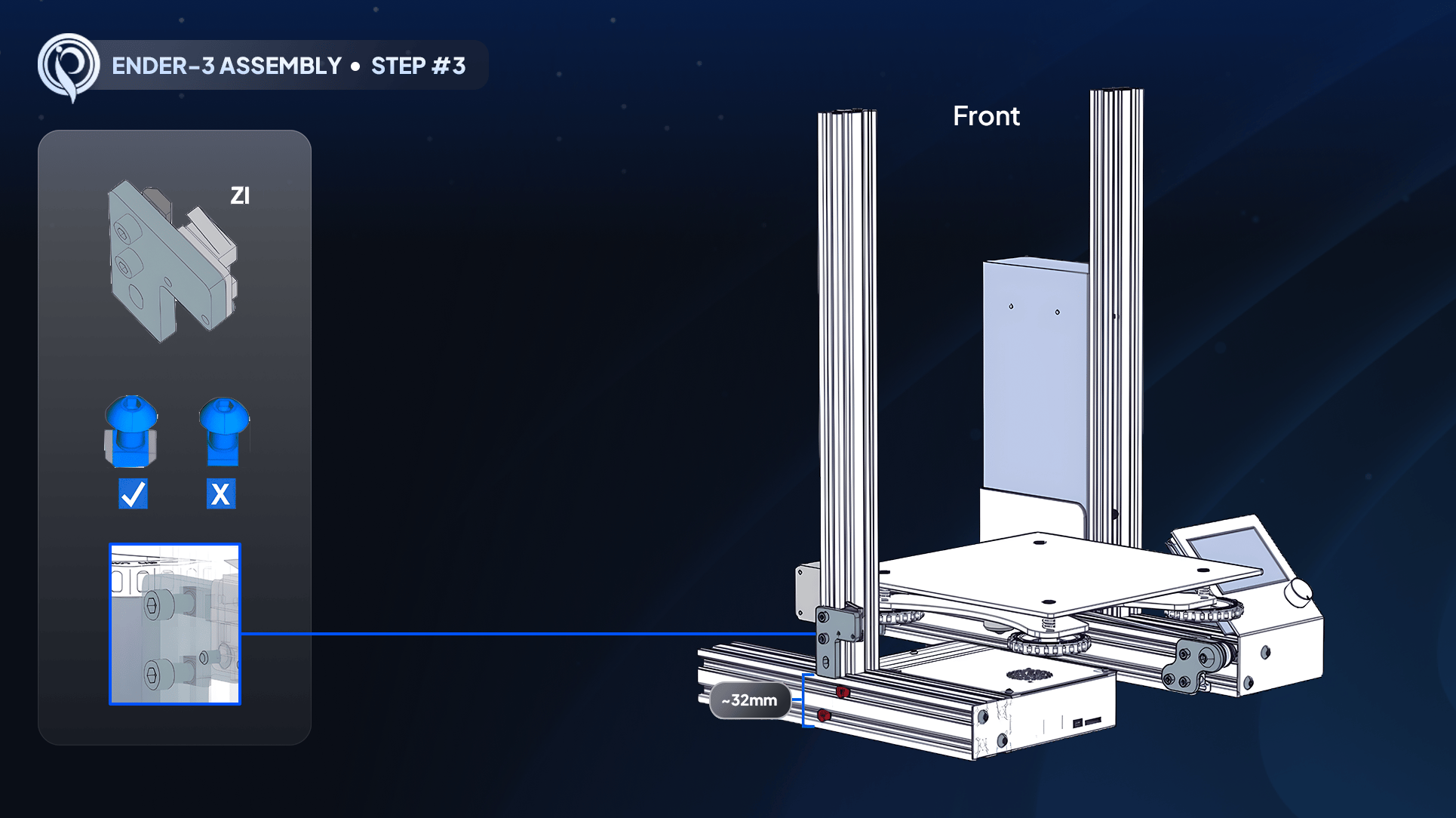
Step 3: seating the limit switch with T-nuts
How T-nuts work
A T-nut slides into the slot of an aluminum rail while vertical, then locks in place when you tighten its screw. This is how many parts attach to the frame without drilling.Step-by-step
1
Loosen the T-nuts
With the number 4 Allen wrench, loosen each T-nut’s screw just enough to rotate the nuts from horizontal to vertical so they can enter the rail slot. Do not remove them.
2
Orient the switch
Hold the switch so the click button points up toward the ceiling, with the T-nuts vertical and facing the rail.
3
Slide it into the rail
Insert the vertical T-nuts into the outer rail slot just behind the Z-axis motor and slide it down until a small plastic stop halts it.
4
Tighten to lock
Tighten both screws with the number 4 Allen wrench. The T-nuts rotate and grip the rail. Wiggle it to confirm it is locked, and press the click switch to confirm it moves freely.
The limit switch is locked in the left rail behind the motor, the click button faces up and clicks freely, and the switch does not wiggle.