> ## Documentation Index
> Fetch the complete documentation index at: https://stem-docs.intellectualpoint.com/llms.txt
> Use this file to discover all available pages before exploring further.
# Frame: side rails
> Identify the two gantry rails and bolt them to the printer base to form the vertical frame.
## Building the frame
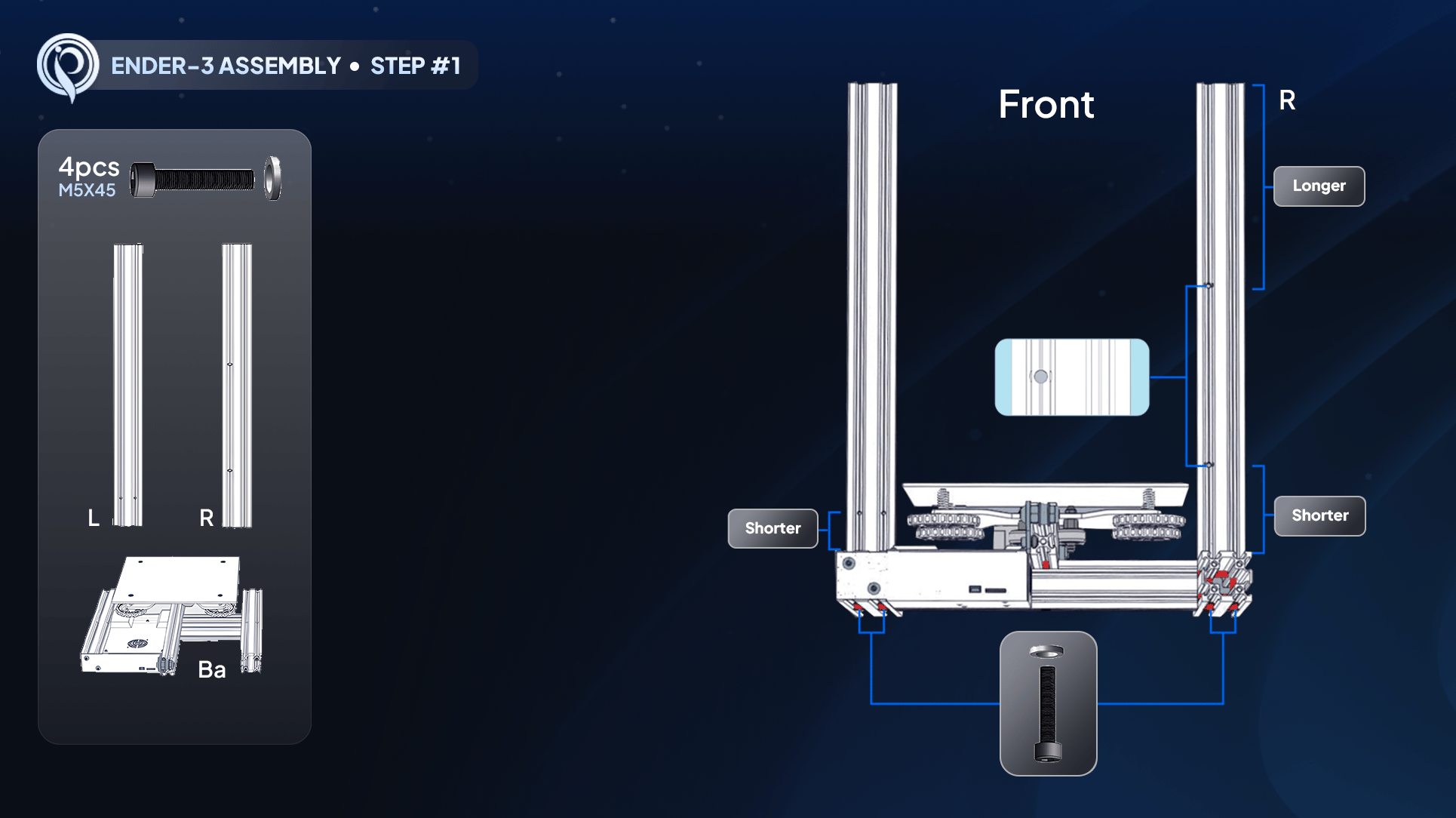
The first assembly step is mounting the two **vertical side rails** onto the printer base. These form the gantry that will carry your print head up and down. Getting the correct rail on the correct side now is critical for everything that follows.
For this step you need the **two M5x45 screws** (the long ones) and the **number 5 Allen wrench** (the largest).
 ## Unwrap and identify the rails
Carefully slit the cellophane along each rail with scissors, cutting away from your body. A small loose screw may fall out of one rail - set it aside (it is only there for shipping). Watch the sharp edges.
The rails are **not identical**. One has **two screw holes on the same track, about eight inches apart** - this is the **right** rail. The other has **two holes near the bottom in separate tracks** - this is the **left** rail.
## Mount the right rail
Move the printer base to the center of your workspace. Face the **dragon/Ender logo** toward you - that is the **front**. The LCD will go on the right.
Take the rail with two holes on the same track and set it on the **right** side, holes closest to the inside (toward the bed) and near the bottom.
Tilt the printer to access the bottom. Push an **M5x45** up through the base hole and into the bottom of the rail. Hand-thread it, add the second screw, then tighten both fully with the number 5 Allen wrench until the heads sit flush and the rail does not wiggle.
## Mount the left rail
Take the remaining rail (two holes near the bottom, about one inch up) and set it on the **left** side, holes toward the inside.
Tilt the printer, push M5x45 screws up through the base into the rail, hand-thread both, then tighten fully. The screw heads should disappear flush into the track.
Both rails are bolted on with no wiggle, the screw heads sit flush with the bottom of the base, the two-holes-same-track rail is on the **right**, and the two-holes-near-bottom rail is on the **left**. Give each a firm wiggle to confirm.
Return your Allen wrench to your tool area after each step. A lost hex key stops your build, and they are not individually replaceable.
## Up next
With the frame standing, the next step is mounting the **power supply** onto the right rail.
## Unwrap and identify the rails
Carefully slit the cellophane along each rail with scissors, cutting away from your body. A small loose screw may fall out of one rail - set it aside (it is only there for shipping). Watch the sharp edges.
The rails are **not identical**. One has **two screw holes on the same track, about eight inches apart** - this is the **right** rail. The other has **two holes near the bottom in separate tracks** - this is the **left** rail.
## Mount the right rail
Move the printer base to the center of your workspace. Face the **dragon/Ender logo** toward you - that is the **front**. The LCD will go on the right.
Take the rail with two holes on the same track and set it on the **right** side, holes closest to the inside (toward the bed) and near the bottom.
Tilt the printer to access the bottom. Push an **M5x45** up through the base hole and into the bottom of the rail. Hand-thread it, add the second screw, then tighten both fully with the number 5 Allen wrench until the heads sit flush and the rail does not wiggle.
## Mount the left rail
Take the remaining rail (two holes near the bottom, about one inch up) and set it on the **left** side, holes toward the inside.
Tilt the printer, push M5x45 screws up through the base into the rail, hand-thread both, then tighten fully. The screw heads should disappear flush into the track.
Both rails are bolted on with no wiggle, the screw heads sit flush with the bottom of the base, the two-holes-same-track rail is on the **right**, and the two-holes-near-bottom rail is on the **left**. Give each a firm wiggle to confirm.
Return your Allen wrench to your tool area after each step. A lost hex key stops your build, and they are not individually replaceable.
## Up next
With the frame standing, the next step is mounting the **power supply** onto the right rail.