> ## Documentation Index
> Fetch the complete documentation index at: https://stem-docs.intellectualpoint.com/llms.txt
> Use this file to discover all available pages before exploring further.
# Mount the extruder bar
> Lift the assembled extruder bar onto the gantry rails and thread it onto the lead screw.
## Putting the gantry together
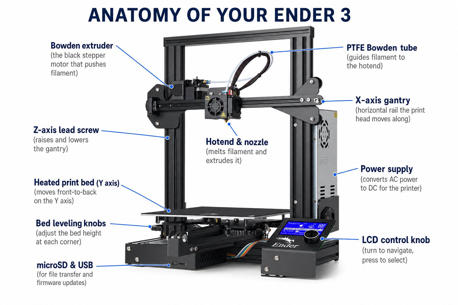
Now you lift the whole assembled **extruder bar** onto the two upright rails. Three things must align: the rollers onto each rail, and the lead screw into the feeder's threaded hole.
 ## Step-by-step
Hold the bar level and set each pair of rollers into the V-slot of the left and right upright rails. It should rest on top of both rails.
The lead screw needs to enter the **golden threaded hole** on top of the filament feeder. Gently push the bar down; when it stops, guide the screw into the hole and **turn the lead screw** by hand - the bar will thread down onto it.
The cables and white PTFE tube must run up and over toward the **back**. If any wire is trapped under the bar, lift the bar off and reroute it.
Turn the lead screw by hand - the bar should rise and lower smoothly. Do not force it.
The extruder bar rides on both rails, threads onto the lead screw, moves up and down smoothly when you turn the screw, and all wires run to the back.
That lead screw is the whole Z axis in action - turning it raises the print head one layer at a time during a print. Seeing it work by hand makes the "layer by layer" idea concrete.
## Up next
Next you install the **belt** that drives the print head left and right.
## Step-by-step
Hold the bar level and set each pair of rollers into the V-slot of the left and right upright rails. It should rest on top of both rails.
The lead screw needs to enter the **golden threaded hole** on top of the filament feeder. Gently push the bar down; when it stops, guide the screw into the hole and **turn the lead screw** by hand - the bar will thread down onto it.
The cables and white PTFE tube must run up and over toward the **back**. If any wire is trapped under the bar, lift the bar off and reroute it.
Turn the lead screw by hand - the bar should rise and lower smoothly. Do not force it.
The extruder bar rides on both rails, threads onto the lead screw, moves up and down smoothly when you turn the screw, and all wires run to the back.
That lead screw is the whole Z axis in action - turning it raises the print head one layer at a time during a print. Seeing it work by hand makes the "layer by layer" idea concrete.
## Up next
Next you install the **belt** that drives the print head left and right.